- Produits
- Solutions
-
Ressources
- EVO-START LTE — Découvrez le plein contrôle mobile
- EVO-START LTE — Sécuriez et protégez vos actifs mobiles
- EVO-START LTE — Suivi GPS et gestion de flotte
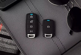
- EVO-9-SERIES — Contrôlez à distance avec style
- EVO-4-SERIES — La meilleure valeur sur le marché
- Harnais en T — Facilitez, accélérez et sécurisez vos branchements
-
Voir toutes les ressources

- Soutien
- Où acheter
 EVO-4-SERIES
 EVO-9-SERIES
 EVO-START
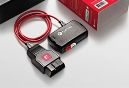 FlashLink Mobile
 Audi
Audi
 Buick
Buick
 Cadillac
 Chevrolet
 Ford
Ford
 GMC
GMC
 Hyundai
 Kia
Kia
 Mazda
Mazda
 RAM
RAM
 Subaru
 Toyota
 Volkswagen
 Trouver nos produits
  Commander nos produits en ligne
 Trouver un
 -
Produits

Produits

-
Contrôles à distance et applications pour la gestion de flotte
-
Modules de contrôle à distance et de contournement de clé à puce
-
Ensembles de type tout-en-un
-
Ensembles EVO-RS avec harnais en T inclus
-
Accessoires d'installation
-
Câble de type harnais en T
-
Outils d'installation et de programmation
-
EVO-GEAR
-
Produits discontinués
-
Voir tout les produits
-
-
Solutions
-
Ressources
Ressources
-
EVO-START LTE — Découvrez le plein contrôle mobile
-
EVO-START LTE — Sécuriez et protégez vos actifs mobiles
-
EVO-START LTE — Suivi GPS et gestion de flotte
-
EVO-9-SERIES — Contrôlez à distance avec style
-
EVO-4-SERIES — La meilleure valeur sur le marché
-
Harnais en T — Facilitez, accélérez et sécurisez vos branchements
-
Voir toutes les ressources
-
-
Soutien
-
Où acheter
-
À propos


