- Products
- Solutions
-
Resources
- EVO-START LTE — Experience Full Mobile Control
- EVO-START LTE — Secure And Protect Your Mobile Assets
- EVO-START LTE — GPS Tracking And Fleet Management
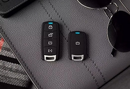
- EVO-9-SERIES — Go The Distance In Style
- EVO-4-SERIES — The Best Value On The Market
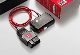
- OEM-Style T-Harness Cables — Connect in a Click
-
View All Resources

- Support
- Where to buy
 EVO-4-SERIES
 EVO-9-SERIES
 EVO-START
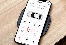
 FlashLink Mobile
 Audi
Audi
 Chevrolet
 Ford
Ford
 GMC
GMC
 Honda
Honda
 Hyundai
 Kia
Kia
 Mazda
Mazda
 Nissan
 RAM
RAM
 Subaru
 Toyota
 Volkswagen
 Find Our Products
  Order Our Products Online
 Find an
 -
Products

-
Solutions
-
Resources
Resources

-
EVO-START LTE — Experience Full Mobile Control
-
EVO-START LTE — Secure And Protect Your Mobile Assets
-
EVO-START LTE — GPS Tracking And Fleet Management
-
EVO-9-SERIES — Go The Distance In Style
-
EVO-4-SERIES — The Best Value On The Market
-
OEM-Style T-Harness Cables — Connect in a Click
-
View All Resources
-
-
Support
-
Where to buy
-
About us
About us


